Reading Modbus Data with ControlCom Edge Server
The ControlCom Connect platform allows fully configuring a onboarded device Edge Server configuration to read Modbus data.
Prerequisites
- This guide requires the ControlCom Edge Server to be onboarded. See our Onboarding Guide for the Edge Server to get started.
Creating a variable
To create a new variable in ControlCom Connect:
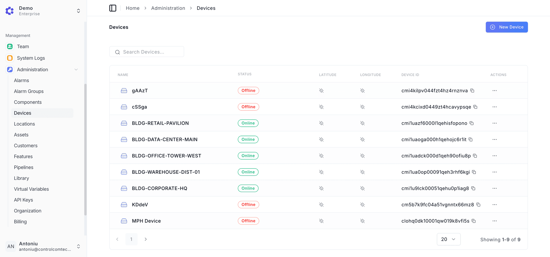
- Navigate to Administration > Devices
- Select a onboarded device
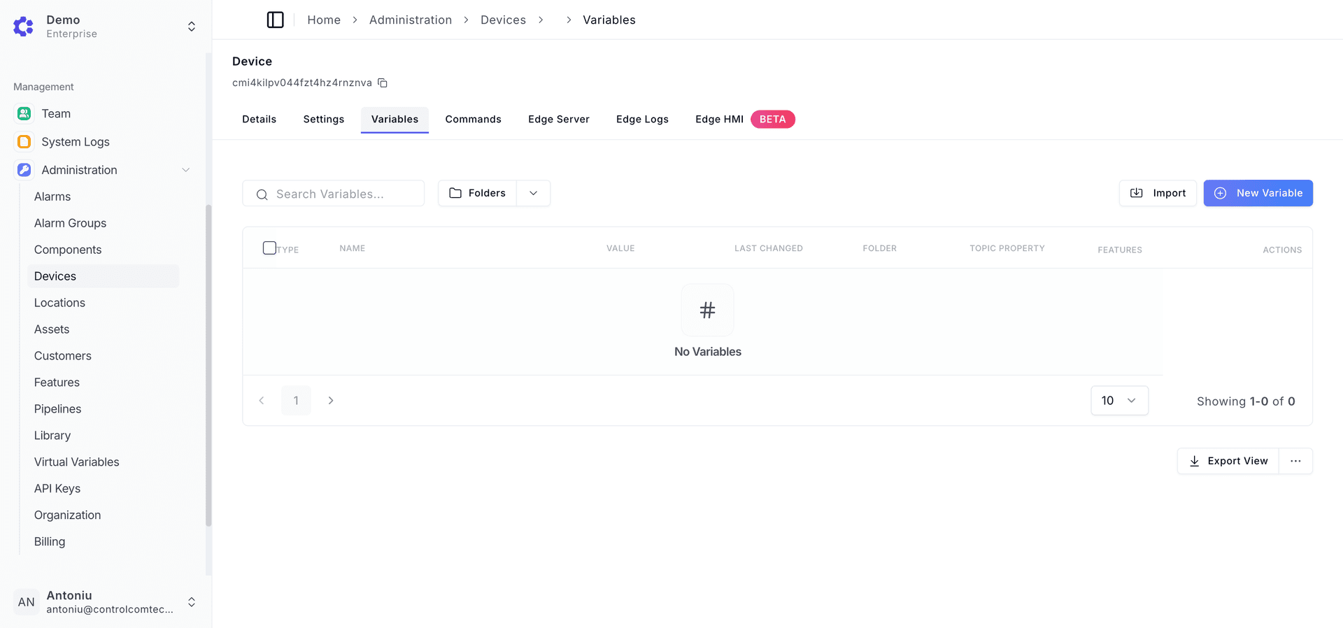
- In the device page, click the Variables tab
- Click the "+ New Variable" button
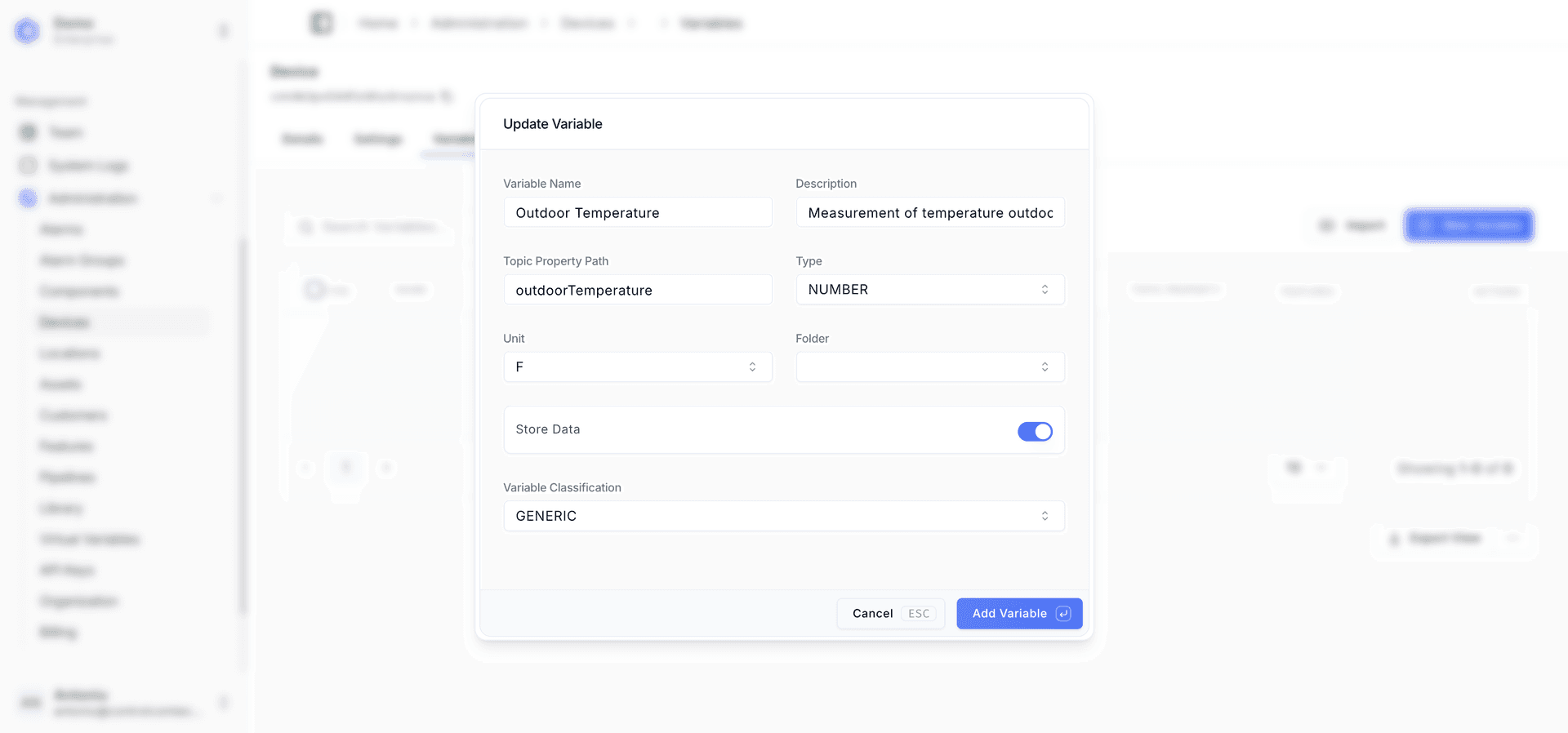
- Enter the Variable Name, Description, Topic Property path
- Select the Type of the data with options boolean, number, or string.
- Enable the Store Data toggle if wanting to view historical values through Visualization
- Important Note If Store Data is disabled, it will still allow live data to come into the system for viewing, but the system will not save the data and you will not be able to visualize it
- Click the "Add Variable" button
Creating a Modbus Client
To create a new modbus client in ControlCom Connect for device:
- Navigate to Administration > Devices
- Select a onboarded device
- In the device page, click the Edge Server tab
- Click the "+ Add Client" and select Modbus TCP or Modbus RTU (For this guide, use Modbus TCP)
- Important Note If using Modbus RTU, the ControlCom Edge Server requires a volume mount to the location of the device which this guide does not cover.
- A new subitem will appear called "Clients", select the newly added client.
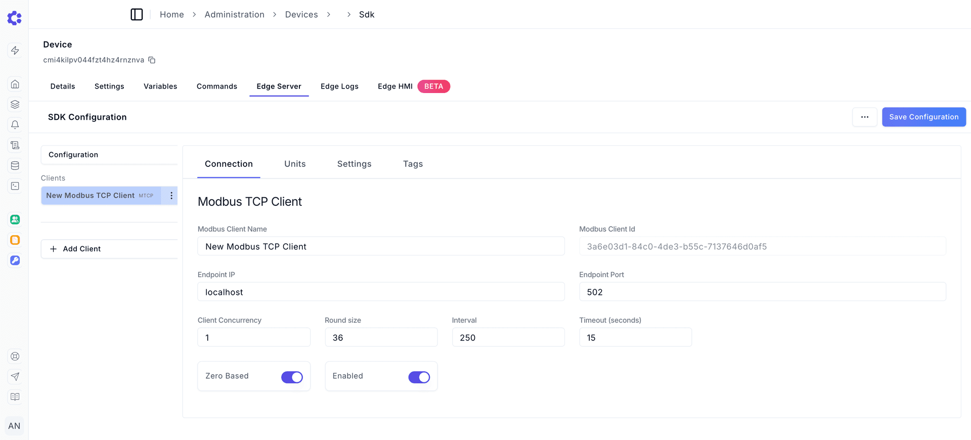
Connection Sub Menu
- Enter in a friendly name for the Modbus Client Name
- Enter the Endpoint IP (local network of modbus device to read from) such as 192.168.1.1 or localhost
- Enter the Endpoint Port (typically 502 for Modbus TCP)
- Set Client Concurrency to 1
- Set Round size to 36
- Set Interval to 1000
- Set Timout to 15
- Enable or disable Zero Based depending on Modbus device.
- Enable the Enabled toggle to enable the client
Connection Client Configuration
Client Concurrency is how many simultaneous Modbus requests can be in flight.
Round Size The maximum number of consecutive registers to read in a single Modbus request.
Interval How often in milliseconds to poll Modbus devices for data.
Timeout Maximum time in seconds to wait for a Modbus response before considering the request failed.
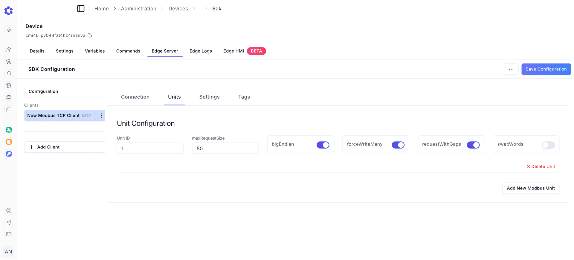
Units Sub Menu
- Click the "Add New Modbus Unit" button
- Enter the expected Unit ID
- Depending on the Modbus device, toggle between Big Endian and Little Endian. If Big Endian is expected, toggle bigEndian to the on position.
- Depending on the Modbus device, toggle swapWords on or off. This configures the byte order configuration when reading 32-bit or larger data types.
- Example
Example: 32-bit float value 0x12345678

Normal order: Register 1 = 0x1234, Register 2 = 0x5678
Swapped words: Register 1 = 0x5678, Register 2 = 0x1234
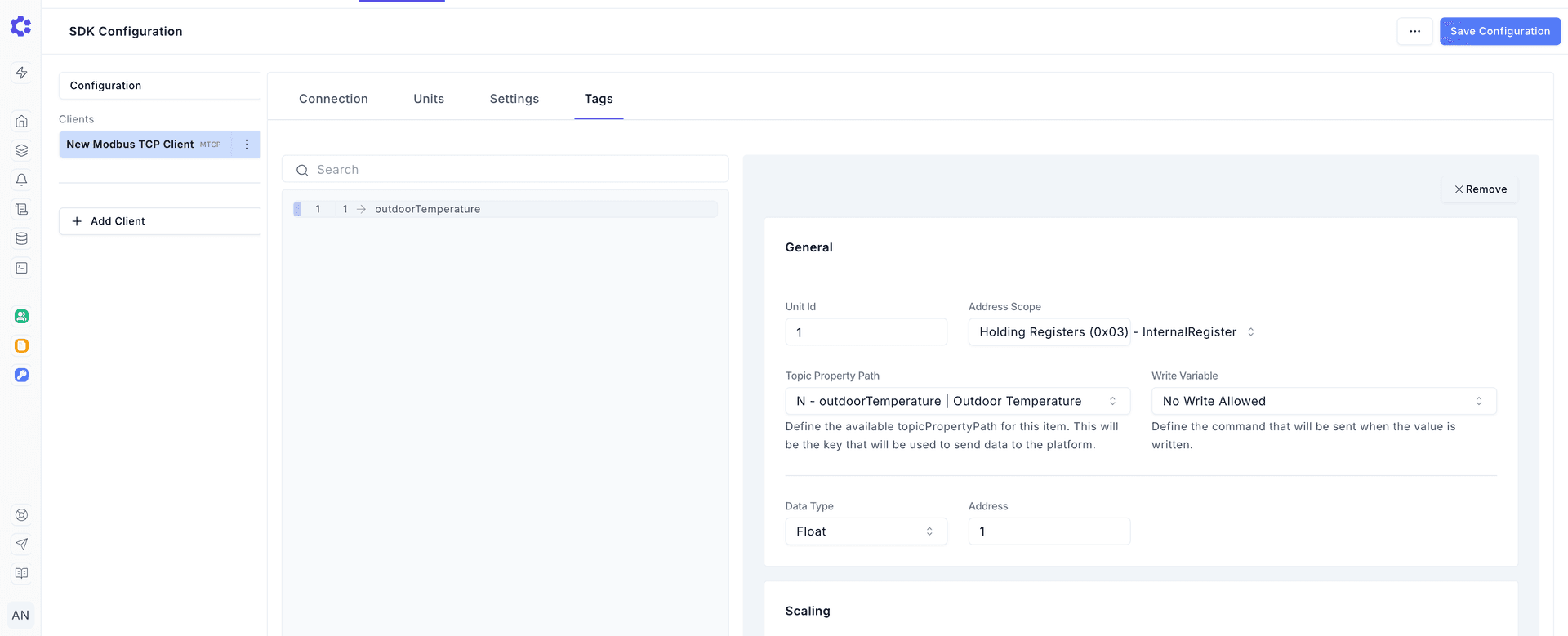
Tags Sub Menu
- Click the "+ Add Item"
- Select the created item in the list of tags window
- Enter the expected Unit ID (defaults to 1)
- Select the Address Scope for the data either Coils/Physical State, Discrete Inputs/Internal State, Input Registers/Physical Register, or Holding Registers/Internal Register
- Select the Topic Property Path (this is the Variable created earlier in the guide)
- Select the Data Type for the Modbus register(s)
- Enter the expected address where the data to be read is located
- Example If the full address is 400001 for the data, then the address is 1 as a Holding Register/Internal Register.
- Set the scale of the value (defaults to 1). If the data is reading as 857, but the expected is 8.57, set the scale to 0.01.
- Set the offset of the value (defaults to 1). It is a constant value added or subtracted from the raw register value to shift the final result.
- Set the decimals of the value (defaults to 2). How many decimals should the read value contain
Saving
After configuring Connection, Units, and Tags, click the "Save Configuration" button and click "Save" in the confirmation popup.
Deployment
Once the Edge Server has been configured to read from a Modbus client, the changes can be deployed in a few ways. The Edge Server will pick up its changes on the next boot of the container.
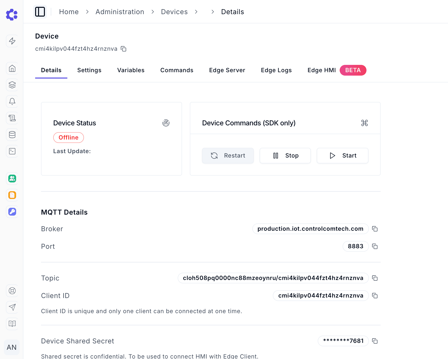
Sending restart command from ControlCom Connect Platform
- Navigate to Administration > Devices
- Select the Device with the new Modbus configuration
- On the Details tab, click the restart button. This will stop the instance where it is currently running.
Stopping and starting the ControlCom Edge Server manually
This can be done by following the restart commands from the Onboarding Guide of the Edge Server